The BBK @ibox H2 is another device that I had previously played with, one of my classmate had it, so I’m interested in seeing it again. It also uses the JZ4740-series Ingenic SoC. With the knowledge and skills that I now have, I should be able to reverse engineer its software, then emulate it using QEMU without having access to the hardware.
Its software is surprising difficult to reverse engineer. Here I recorded the steps I took to understand its software architecture, and I’ve learned quite a few new things in the process.
Finding software packages
The JZ4740-series Ingenic SoCs have easy to access USB boot method without any security checks, using that we should be able to dump out system’s flash storage, if we had the hardware.
However, since I do not have the device, let’s check what kind of update or recovery packages are available.
The “视频学习机_@iboxH2_V2.2L_超级系统恢复” is an interesting target. It is a PC-based recovery software, looks like the recovery is done using the aforementioned USB boot method. Let’s install it somewhere and find its contents:
I have documentation for JZ4740 and JZ4750, but unfortunately not JZ4750L. Later while emulating it, I found out that it’s a mixture of the two, mainly JZ4750.
We do have JZ4750L mentioned in one of Ingenic’s Linux kernel source code patches (linux-2.6.24.3-jz-20100304.patch.gz), the header files for JZ4750L is going to be very useful for finding out IRQ index and available peripherals.
System images are encrypted
Whether the SoC loads from NAND or MMC, it must load the first stage loader of 8KiB into internal SRAM, then starts executing there.
The file sizes of data0.dat and data0_L.dat look like it could be used for this purpose, however it seems they are encrypted:
1
2
3
4
5
$ ent data0.dat Entropy = 7.974006 bits per byte.
Optimum compression would reduce the size of this 7112 byte file by 0 percent.
A simple entropy check shows file’s data is almost random, likely either encrypted or compressed.
Usually for an executable binary, entropy should be much less, e.g. Noahedu NP1300 u-boot binary:
1
2
3
4
5
$ ent np1380/segment01.bin Entropy = 3.802258 bits per byte.
Optimum compression would reduce the size of this 960316 byte file by 52 percent.
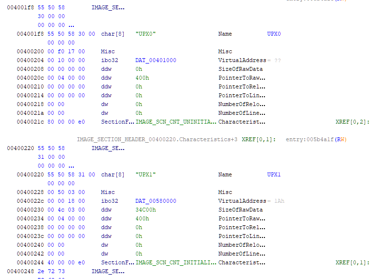
binwalk could not find any recognisable compression headers, so it is likely encrypted.
Except for data1*.dat, all other data*.dat files are also encrypted. data1*.dat looks like some sort of index file, so not super useful.
Next we must check the USB recovery process to understand how to decrypted these files.
USB recovery process
Windows executable
Loading the Windows executable super_recover.exe into Ghidra, the disassembled entry function looks super complicated:
Reading about the USB boot process “33.5 USB Boot Specification”, the first step is to load a small binary blob into SRAM, less than 16 KiB, to initialise the on-board SDRAM and storage.
As their name suggests, usb_init_16M.bin and usb_init_16M_Ex.bin seems to be used for this purpose.
We can also find references to them in the Windows executable at function offset 0x00470854:
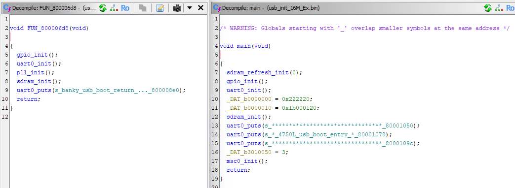
JZ4750 SRAM is located at address offset 0x80000000, we can load these binaries at these address and confirm using Ghidra:
The function names are assign by me, we can figure out what these functions does by checking which hardware peripheral registers it accesses.
Again we see a string confirming that usb_init_16M_Ex.bin should be used on the JZ4750L SoC. It initialises MSC0, so system storage is probably emulated MMC connected to MSC0.
usb_init_16M.bin maybe used on a different hardware revision, we’ll find out later.
Second stage program
After SDRAM is initialised, we can load a larger binary that can do a lot more things, like actually writing to system storage.
These binaries are very likely used for that based on their names:
BurnSys_@IboxH2_V2.0.bin seems to be the final program used for writing data files to system storage, let’s take a look at it. Load address 0x80b04000 is also mentioned in the Windows executable.
Decrypt executable binary data files
In BurnSys_@IboxH2_V2.0.bin there are some GBK-encoded strings referring to buffer decryption:
It initialises SDRAM, MSC0 and some other peripherals, then starts loading next stage data from SD or MMC card connected to MSC0. All as expected for a first stage loader.
So, for emulation, we will need to prepare an SD/MMC image, with data0_L.dat placed at the very beginning.
Interestingly it seems to implement an AB partition switching mechanism, using RTC Hibernate Scratch Pattern Register (HSPR) to switch between them. One partition is located at 0x0c00 block offset (0x00180000: 1.5 MiB), another one at 0x8400 block offset (0x01080000: 16.5 MiB), size 0x0d48 block (0x001a9000 / 1700 KiB). Load and entry address is 0x80004000.
Kernel
Loading decrypted data2_L.dat into Ghidra at address 0x80004000, we also get good looking disassembly results, e.g.:
It must be the data loaded by the first stage loader. For emulation, we will need to copy data2_L.dat to both partitions, offsets 0x00180000 and 0x01080000.
How it loads other data is not clear from a quick look at the code. Let’s try to run the code in QEMU.
JZ4750L MSC0 boot
Following JZ4750 programming manual “33.6 MMC/SD Boot Specification”, I’ve made a bootrom that loads 8 KiB of data from MSC0 into 0x80000000, and starts executing there.
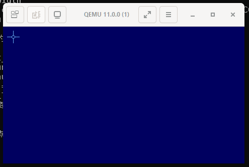
However, this didn’t work, SoC seems to keep rebooting from bootrom code.
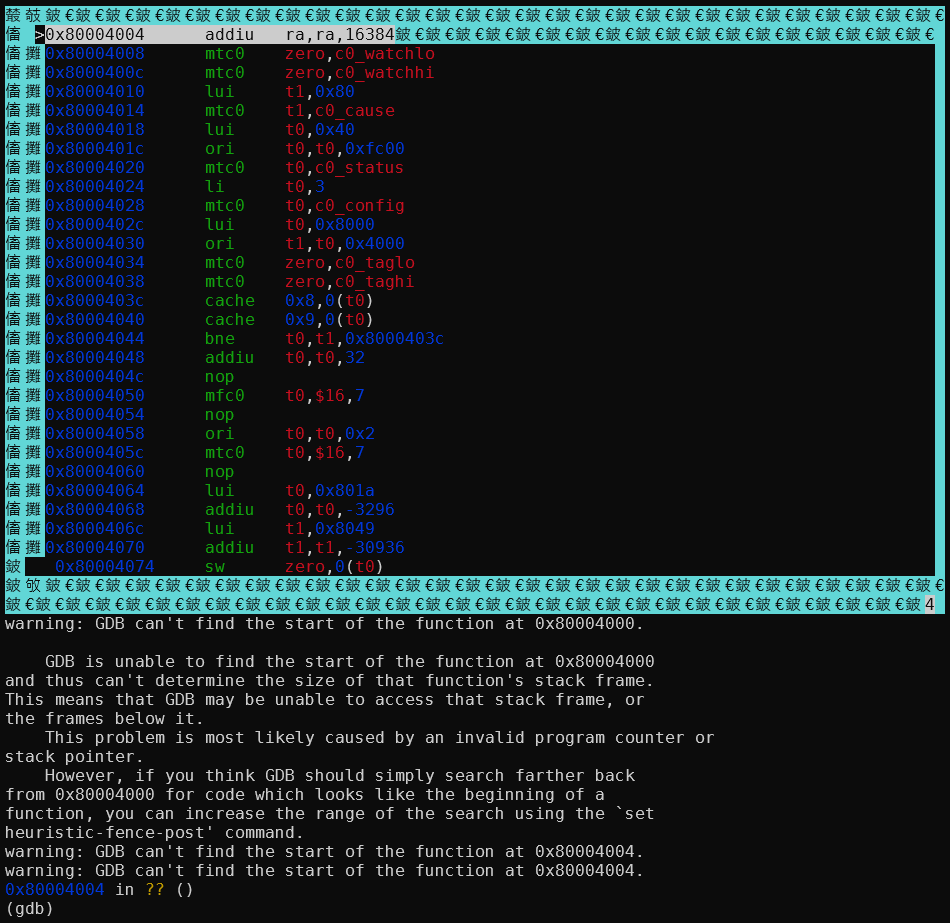
Attach gdb to QEMU, set a breakpoint at 0x80000000, we can see that code could not be disassembled, but later instructions are fine:
Attempting to single step through an instruction does not work. Instead of continuing execution, CPU seems to jump to an interrupt somewhere else, probably because of illegal instruction exception.
Enabling QEMU in_asm log, we can see that QEMU also does not understand the code at 0x80000000, and jumps to somewhere else:
The data at 0x80000000 in ASCII says LPSM, no idea what it means. JZ4750 programming manual says CPU should start execution at address 0x80000000. I also have another device (Noahedu NP6800) that uses JZ4750 with MSC0 boot mode, that device’s first stage loader does have a valid instruction at 0x80000000. This is probably a quirk with JZ4750L that it starts execution from 0x80000004 instead.
Easy fix in the bootrom, the first stage loader then runs correctly.
gdb breakpoint commands
I was hoping that these loader code would print debug messages to one of the UART peripherals. However, looking inside the debug print functions, they are just.. empty 😞.
For example, the debug print function at offset 0x80000270 in data0_L.dat:
1 2 3 4
voiddbg_print(char *p_str) { return; }
It’s lucky that the debug print calls were not optimised out, otherwise losing all the debug strings would make reverse engineering much more difficult. Guess Link-Time Optimization (LTO) was not available or not enabled at that time (LTO sometimes still does not work correctly nowadays).
But now, we need to find a way to get these strings printed.
One possible solution is to somehow patch the binary to print them to a UART, but that is rather difficult.
Alternatively, the method I went with is to attach gdb to QEMU, set up breakpoint at these functions, then print the function argument register inside the gdb session.
Some more googling later, I came up with this gdb script:
1 2 3 4 5 6
b *0x80000270 commands silent printf"%s", $a0 c end
This can be simplified to a simple dprintf command:
1
dprintf *0x80000270, "%s", $a0
It is also possible to print out where the function was called by printing out the $ra register, like this:
Being able to insert prints and other commands after a breakpoint provided to be super useful for reverse engineering.
gdb character encoding
Like any modern Linux system, my terminal is set to UTF-8 encoding, but these older Chinese devices like ibox-H2 generally uses GB2312/GBK as their main character set. So we need to do character encoding conversion.
Luit is a filter that can be run between an arbitrary application and a UTF-8 terminal emulator. It will convert application output from the locale’s encoding into UTF-8, and convert terminal input from UTF-8 into the locale’s encoding.
However, this garbles the nice CUI borders around gdb assembly code listing. There is probably a solution but I can turn off CUI for now, a small price to pay. For disassembly I usually look at Ghidra anyway.
JZ4750L interrupts
Interrupt index
After booting the MSC0 image, it soon got stuck initialising MSC0.
1 2 3
=========================== Mmc_controller.c CpmSelectMscHSClk:clock = %d,div = %d,A_CPM_MSCCDR[0x%x] set clock to %u Hz is_sd=%d clkrt=%d A_MSC_CLKRT[0x%x]
With ingenic_msc_* trace enabled in QEMU, I can see that it has enabled MSC0 interrupts, and an interrupt has happened, but nothing afterwards:
I had interrupts connected as in JZ4750 documentation, but apparently JZ4750L interrupts are connected differently. Since we don’t have JZ4750L documentation, the only information we have is the Linux kernel source code patch. Fortunately, it does tell us how the interrupts are connected:
Interestingly, there are 2x DMAC interrupts. JZ4750 does have 2x DMA controllers, but only one interrupt connected. So this part in the JZ4750L is different to JZ4750.
Easy fix, or so I thought.
Filesystem
At least with interrupt index fixed, MSC0 initialisation completes successfully. Kernel tries to load some resource files, but failed:
After fixing some issues with LCD descriptor, I have LCD output as well:
It looks like a touchscreen calibration process, but there is no way the display would look that primitive. It’s probably because it failed to load the resource files, let’s check how it finds resource files.
File packets
Two of the largest files from the recovery program are packet1.dat and packet2.dat. Let’s see what’s inside packet1.dat:
Going to address 0x0001f400, that appears to be near where data starts.
1 2 3 4 5
0001F300 00 00 00 00 00 00 00 00 00 00 00 00 00 00 00 00 ................ ... 0001F400 00 00 00 00 00 00 00 00 00 00 00 00 00 00 00 00 ................ 0001F410 56 58 CC CC CC CC E0 01 00 00 10 01 00 00 CC CC VX.............. 0001F420 CC CC CC 10 FF FF FF FF 45 00 45 00 88 00 03 00 ........E.E.....
So that seems to be the offset to file data after global header.
The difference between two file offsets is 0x0005f018 - 0x0001f400 = 0x0003fc18. Exactly same as the first 4 bytes of the first file header. So that seems to be file size.
After file header offset 0x08, there appears to be a string. Decode it using GBK encoding, we get strings like:
Not sure what 20 means, probably describes some sort of file type. Next 8 character hex string, probably some sort of checksum. Then we have the file path.
So we have (0x00014410 - 0x00000010) / 256 + 1 = 325 = 0x00000145 number of files. The 4 bytes starting from offset 0x08 in the global header shows exactly the same number. That should be where number of files is stored.
With these information, we can extract all the files from packet1.dat and packet2.dat. Pictures and audio files all open without issue, text file also looking good, no extra unrecognised data at the end of file. The two packet*.dat files are probably for two different partitions.
Filesystem partitions
Going back to the data2_L.dat kernel binary, let’s check how it initialises the file system. There is this print we can try to follow:
1
====fs_init failed====
It is referenced by the function at 0x80020500:
1 2 3 4 5 6
iVar1 = FTL_Init(0); if (iVar1 == 0) { uVar2 = fs_init(0); if (uVar2 == 0xfffffffe) { dbg_printf(s_====fs_init_failed====_800aef4c); }
Following the fs_init(0) function, eventually I found the function at 0x8003ab60:
So we can see: For partition == 0, it reads from MSC0 at block offset 0x0000f400 (0x01e80000: 30.5 MiB). For partition == 1, it reads from MSC0 at block offset 0x000dec00 (0x1bd80000: 445.5 MiB). For partition == 2, it reads from MSC1.
So it only supports FAT12 and FAT16 file system types. That’s fine, we can create two FAT16 partitions at the block offset we found earlier. Make sure the size is suitable so it doesn’t overwrite later data.
Files from packet1.dat look like system files, so put them in partition 0. And files from packet2.dat look like data files for various programs, so that goes into partition 1.
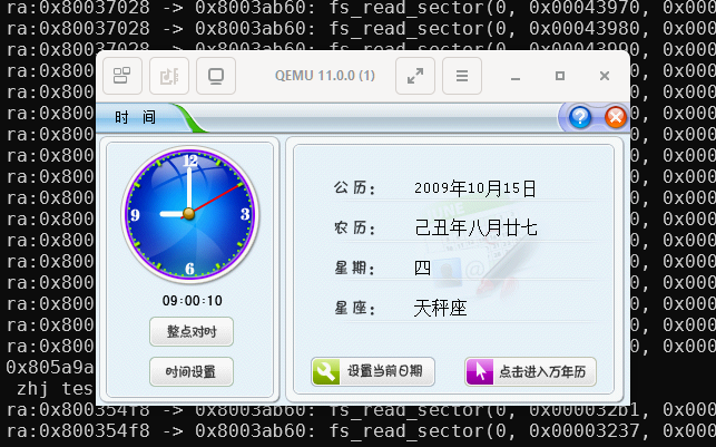
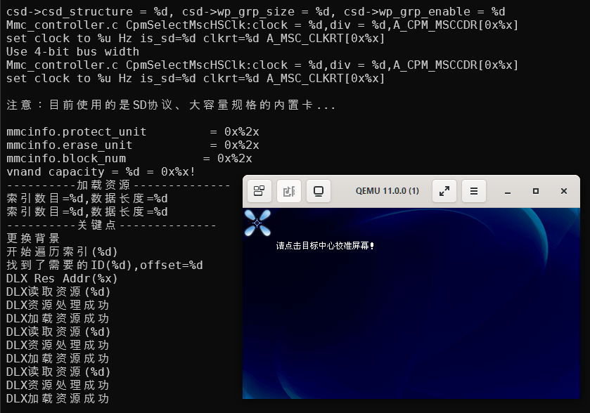
Starting up QEMU again, now the touchscreen calibration screen looks proper:
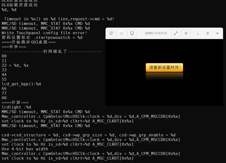
After calibration, it then complains that clock needs to be reconfigured:
However, this doesn’t work, the code just complains endlessly about some sort of exception issue and gets stuck:
Adding more and more debug prints, it seems for the file path A:\系统\数据\Shell\imedat.dlx, it is able to find the drive and the 系统 directory, but unable to find the 数据 directory.
Because FAT16 uses UCS2 encoding for long file support, like UTF-16, each character takes 2 bytes. So we need to enable a temporary UCS2 to GBK charset conversion and use x/sh to print them out.
1 2 3 4 5 6 7 8 9 10 11 12 13
b *0x8002ed6c set$long_name_last = 'a' commands silent set target-charset UCS2 printf"%#010x: long name = ", $pc x/sh $s4 set target-charset GBK if *(unsigned long *)$s4 != 0 || $long_name_last != 0 set$long_name_last = *(unsigned long *)$s4 c end end
1 2 3 4 5 6 7 8 9 10
GUI加载完毕1 0x80045e90: fopen("A:\系统\数据\Shell\imedat.dlx", "rb") strlen(0xcf5c3a41 = "A:\系统\数据\Shell\imedat.dlx") strlen(0xcf5c3a41 = "A:\系统\数据\Shell\imedat.dlx") 0x8002ed6c: long name = 0x809f1720: u"系统" strlen(0xddbefdca = "数据\Shell\imedat.dlx") ra:0x80037624 -> 0x8003ab60: fs_read_sector(0, 0x00000010, 0x00000001, 0x809ece00) ra:0x80037028 -> 0x8003ab60: fs_read_sector(0, 0x00000210, 0x00000040, 0x80cd0080) 0x8002ed6c: long name = 0x809f1720: u"" 0x8002ed6c: long name = 0x809f1720: u""
This is strange, because earlier, it was able to find files like A:\系统\数据\shell\touchpanel.dlx for showing the touchscreen calibration, which sits in the same directory:
1
2
3
4
5
6
7
8
9
10
11
12
13
0x80044784: fopen("A:\系统\数据\shell\touchpanel.dlx", "rb")
strlen(0xcf5c3a41 = "A:\系统\数据\shell\touchpanel.dlx")
strlen(0xcf5c3a41 = "A:\系统\数据\shell\touchpanel.dlx")
0x8002ed6c: long name = 0x809f0ee0:     u"系统"
strlen(0xddbefdca = "数据\shell\touchpanel.dlx")
ra:0x80037028 -> 0x8003ab60: fs_read_sector(0, 0x000001e0, 0x00000010, 0x809eeee0)
0x8002ed6c: long name = 0x809f0ee0:     u"配置"
0x8002ed6c: long name = 0x809f0ee0:     u"数据"
strlen(0x6c656873 = "shell\touchpanel.dlx")
ra:0x80037028 -> 0x8003ab60: fs_read_sector(0, 0x00000df0, 0x00000010, 0x809eeee0)
0x8002ed6c: long name = 0x809f0ee0:     u"26字母.bin"
0x8002ed6c: long name = 0x809f0ee0:     u"alarm.mp3"
...
After a lot more complicated debugging, eventually, I found out that in function 0x800303d8:
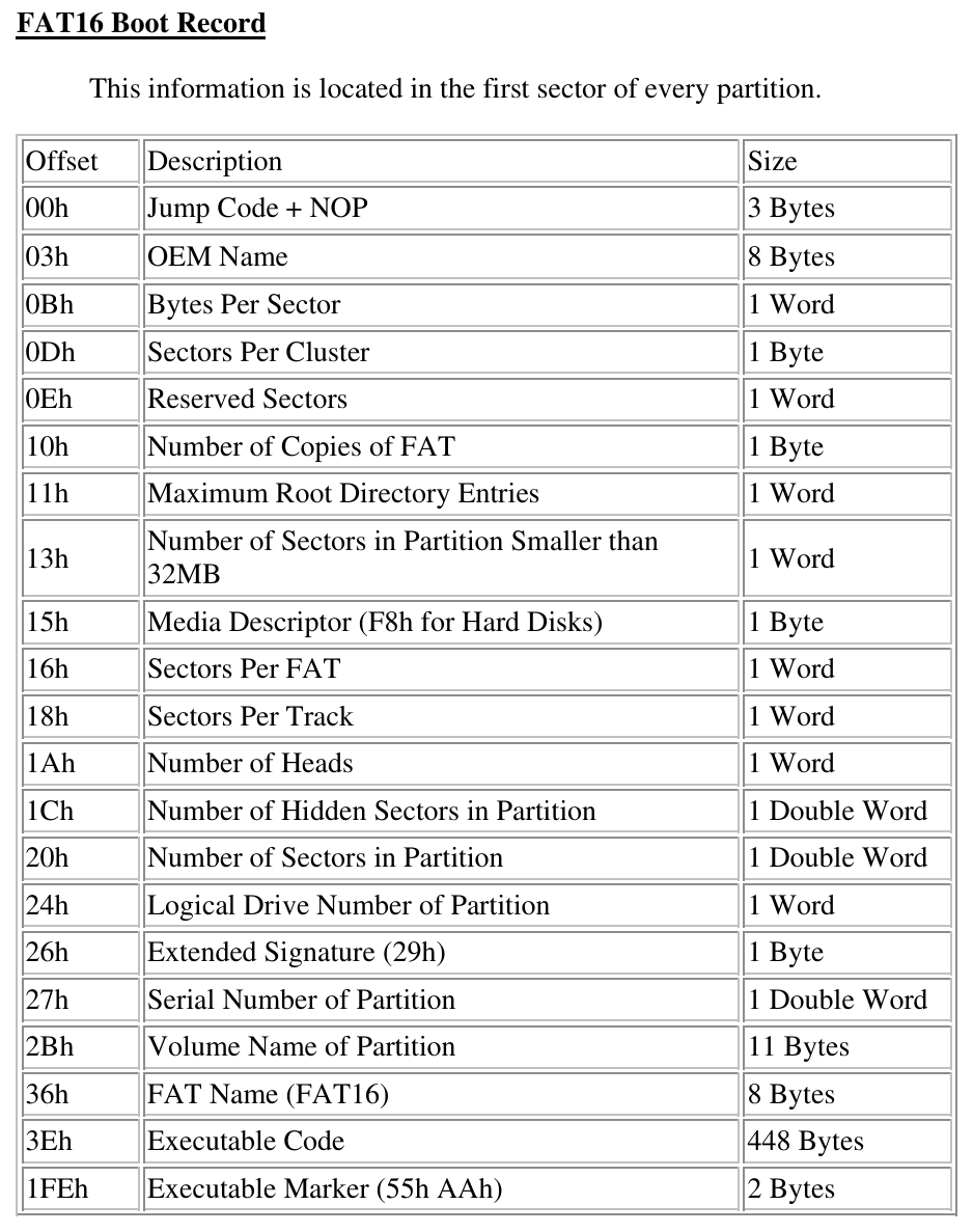
Take a look at FAT16 specs, the field at offset 0x0d means sectors per cluster:
The buggy filesystem driver uses the same global variable for both partitions, we must format both of them with exactly the same parameters 🙄. If someone formats the user data partition on a PC with the wrong parameters, it can breaks the whole system.
I’ve tried to only match the sectors per cluster parameter, however somehow that doesn’t work when partition 1 is larger than 1 GiB. We need to look into how the BBK software formats the partitions, and match it exactly.
The partition formatting function can be found at 0x80032ba0:
It defines two OS programs, with entry addresses at 0x804af000 and 0x8086b000 respectively, loaded from MSC0. Similar to the kernel, it also supports AB switching. One set of block offsets are at 0x2000 (0x00400000: 4 MiB) and 0x6400 (0x00c80000: 12.5 MiB). Another set of block offsets are at 0x9800 (0x01300000: 19 MiB) and 0xdc00 (0x01b80000: 27.5 MiB).
Using Ghidra, we can check that data3_L.dat does load correctly at 0x804af000, and data4_L.dat loads correctly at 0x8086b000. Now we have the data to copy to those block offsets, we can update the MSC0 system image again.
Timer interrupts
Booting again, it progressed further, but still gets stuck in a different way. This time it seems it got stuck in an interrupt handler.
So, timer 0 full comparison match interrupt is pending, but somehow the interrupt handler does not process it. We can check that the software does intend to set up the timer 0 with interrupts enabled, it must be the emulator that’s wrong.
From the code, we can deduct that: TCU0 triggers interrupt handler 21, does not seem used by the BBK software. Guessing it may be used by the OST. TCU1 triggers interrupt handler 22, registered by timer 0 init code. TCU2 is the combined interrupt for timer 1 to timer 5.
It seems JZ4750L requires a new TCU timer model in the emulator, that I can fix. This interrupt connection is different to both JZ4740 and JZ4750.
API calls
The emulator progresses further after timer interrupts fixed, however it still gets stuck at an exception handler:
It loads in the application file A:\应用\程序\中学时间.bda to reconfigure the clock. That file we can find from packet1.dat, but we need to understand how to load it.
The return address 0x804c4c00 sits inside data3_L.dat, not the kernel. So we need to load data3_L.dat into Ghidra to take a look.
The code here looks like it’s trying to call kernel functions by using pointers to arrays of functions. We can find that these pointers are initialised by the function at 0x804afa20:
So the first 0x88 number of bytes in the .bda application files are the file header, encrypted by XOR’ing with *0x80652b14 = 0x44525744. The checksum XOR is *0x80652b1c = 0x322d464b. A couple of magic signature checks at the beginning. And data starting offset can be found at offset 0x14.
Generally, the entry address seems to be 0x81c30040. But there are also a couple of special cases depending on the file path. This is good enough for extracting and loading the executable binary data from the 中学时间.bda application into Ghidra.
SDRAM wrapping and hardware revisions
Now we can check why exception handler was triggered by this application.
The application has a similar structure to the OS program.
First, it also fills in arrays of function pointers:
I could not find any references to this address range in any of the previous programs: first stage loader, kernel and OS program. Then I suddenly realised, if SDRAM is only 32 MiB, accessing this 0x83c30018 address would wrap back to 0x81c30018. 0x81c30018 is also used by the OS program to call kernel API functions, so this makes sense.
Easy fix, reduce SDRAM size to 32 MiB, and:
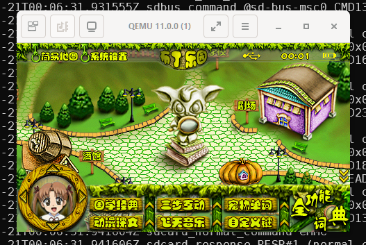
YAY! The application runs!
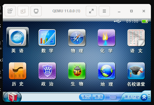
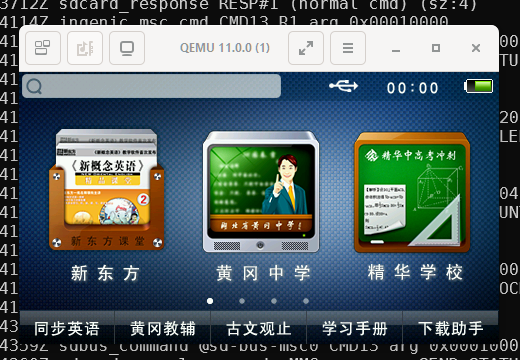
Quit out of the application, the desktop appears:
So, the JZ4750L hardware revision has smaller 32 MiB SDRAM size, that’s interesting. The kernel and OS program code for the JZ4740 hardware revision does make use of RAM addresses like 0x83c30018, so the JZ4740 hardware revision must have a larger 64 MiB SDRAM size.
Hardware revision specific applications
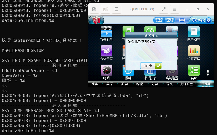
The system settings application actually fails to load:
We can see that the application file path is:
1
0x804c4c00: fopen("A:\应用\程序\中学系统设置.bda", "rb")
Inside 应用/程序 directory from packet1.dat, there isn’t a file named 中学系统设置.bda, but two files instead: 中学系统设置.bda_4720 and 中学系统设置.bda_4750l.
Looks like some .bda files are actually hardware revision specific. The USB recovery tool must have some special handling to rename the files. That’s easy to fix, I can rename the files when writing system image partitions too.
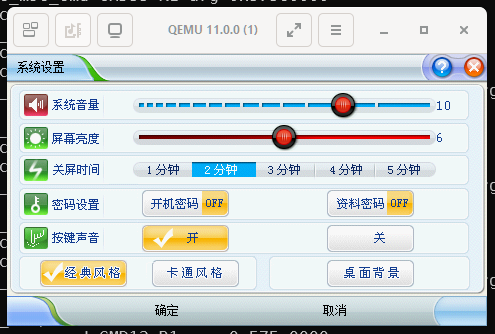
Now it runs fine:
Is RTC time valid?
I’d like to find out how it checks whether current time is valid, so I don’t need to reconfigure clock every time.
This is easy, find the fnGUI_IsRTCTimeValid function at 0x8001d5c4:
The RTC.HSPR register should preserve its content across reboots. Just need to initialise its content as 0x12345678. Note as we discovered earlier, bit 0 is also used for AB partition switching.
JZ4750L CPU identification
The recovery package contains software version V2.20. There is also software version V3.20 available from “视频学习机_H2_V3.20_一卡系统恢复”, I’d like to check it out. Since it is loaded from SD card on MSC1, just need to make a MSC1 image with the update program extracted there.
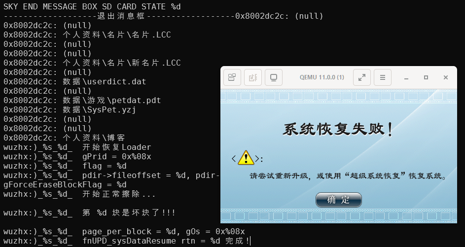
It does prompt for system update straight after booting, however, update fails:
Looking at the log, it appears to be trying to access a non-existent NAND flash? I do know that the JZ4740 SoC must be booting from NAND, so it seems it is confused about the hardware revision somehow. Great, now I need to debug the system update program too.
Extract executable binary from the 系统恢复.bda file, load into Ghidra, following the bad block prints, I came cross this code segment:
So far, I’ve been emulating the CPU.PRId register with value 0x00ad0024f, the value from Ingenic JZ4750 PM 2.2 Extra Features of CPU core. JZ4740 PM also has the same value. Either the document is wrong, or the register value on the JZ4750L SoC is different. I think it is more likely the document is wrong, JZ4750 CPU probably all has 0x01ed0024f.
SD vs. eMMC
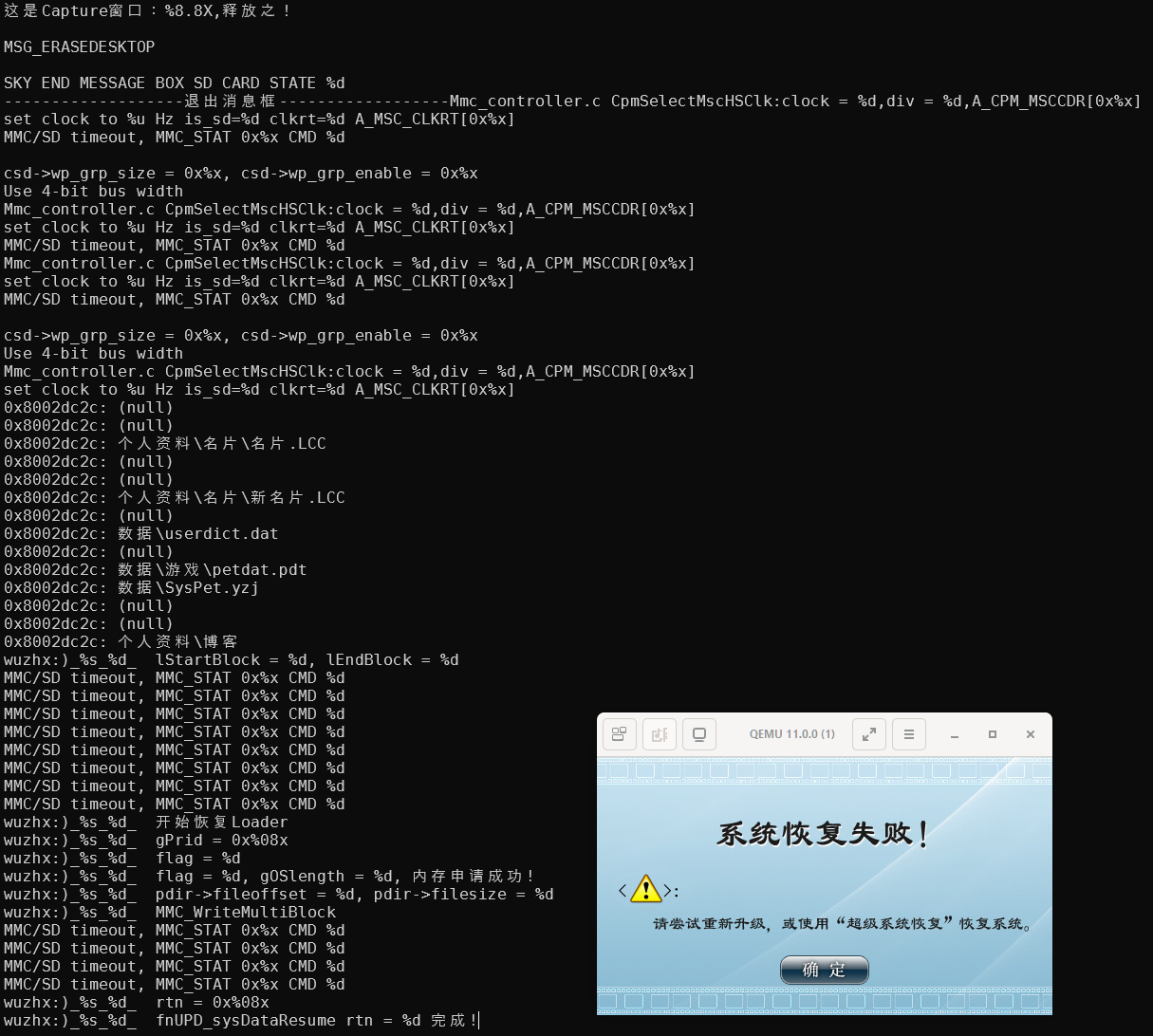
After corrected the CPU.PRId register value, system update still fails, but for a different reason:
// Update program asks the card to publish a new relative address (RCA)
ra:0x81c34c04 -> 0x81c3469c: upg_msc0_cmd(p=0x8039f9e8, cmd=3, arg=0x00000010, nb=0000000000)
// The new RCA is 0x878d0000
ra:0x81c34c04 -> 0x81c3469c: upg_msc0_cmd(p=0x8039f9e8, cmd=9, arg=0x878d0000, nb=0000000000)
// Kernel tries to access the card using RCA = 0xc0260000
ra:0x8003ce34 -> 0x8003ee88: krn_msc0_cmd(p=0x8039efd0, cmd=13, arg=0xc0260000, nb=0000000000)
// That failed, since RCA has been changed by the update program
MMC/SD timeout, MMC_STAT 0x%x CMD %d
// Kernel asks the card to publish a new relative address (RCA)
ra:0x8003f3e8 -> 0x8003ee88: krn_msc0_cmd(p=0x8039efd8, cmd=3, arg=0x00000010, nb=0000000000)
// The new RCA is 0x7b540000
ra:0x8003f3e8 -> 0x8003ee88: krn_msc0_cmd(p=0x8039efd8, cmd=9, arg=0x7b540000, nb=0000000000)
// Update program is still using RCA = 0x878d0000
ra:0x81c32308 -> 0x81c3469c: upg_msc0_cmd(p=0x8039f9c8, cmd=13, arg=0x878d0000, nb=0000000000)
// That failed, since RCA has been changed again by the kernel
MMC/SD timeout, MMC_STAT 0x%x CMD %d
So far, I’ve been using SD card mode for the system image attached to MSC0. Looks like the update program has a separate set of MSC0 access functions, that are conflicting with kernel, by requesting new random RCA as part of SD card initialisation process.
I know that during SD card initialisation process, one of the steps is to check whether the connected card is SD card or MMC. Let’s see how MMC works.
Different to SD card, MMC initialisation CMD3 is SET_RELATIVE_ADDR, host assigns the address, instead of the card generating a random RCA. Perhaps, if kernel and update program always assign the same RCA, MMC won’t complain about timeouts. This feels like a terrible hack, but BBK’s software is probably as horrible as this 🙄.
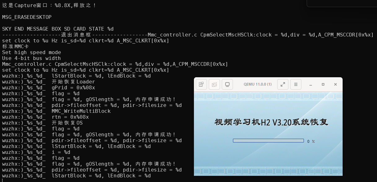
And indeed, switching to eMMC mode works, it’s updating now:
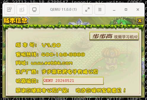
And I get to see the V3.20 system:
In system settings, there is also a cartoon theme mode (using OS program data4_L.dat), that doesn’t seem to have changed much between V2.20 and V3.20:
Serial number encryption
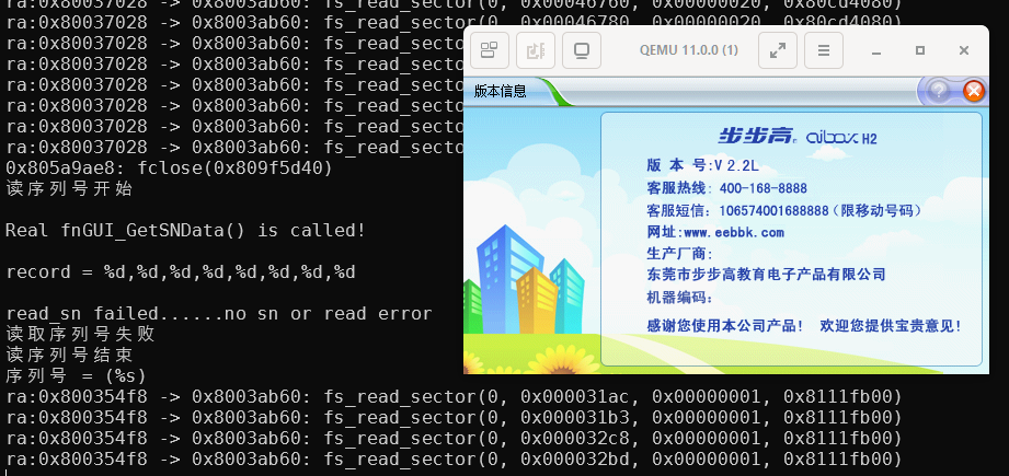
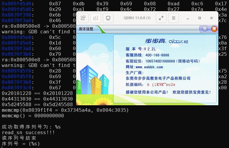
Opening system version information application, it complains about serial number not found:
Let’s go back to V2.20 to debug this, since all the breakpoint addresses I have in gdb scripts are only valid for V2.20.
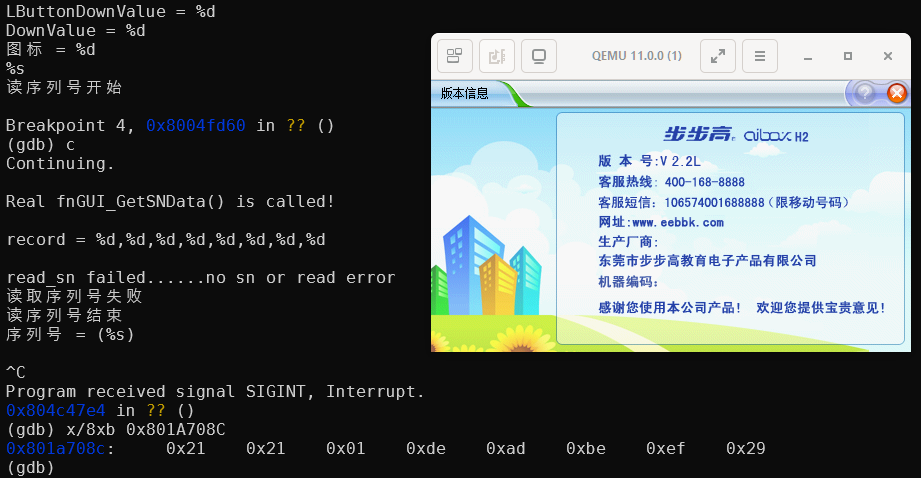
Finding the serial number read function is not difficult, the function is fnGUI_GetSNData() at 0x8004fd60.
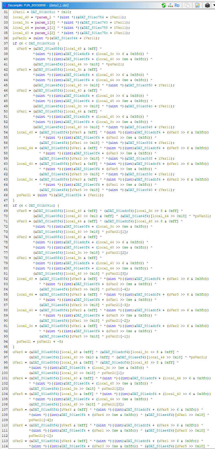
However, the decryption logic inside looks super complicated:
Later, in group chat, my friends are playing with AI tools. As an exercise, we gave it the following prompts, let’s see if AI can figure out how the serial number is encoded:
It is able to recognise functions like malloc, memset, able to recognise MMC access functions, and RTC functions. The most useful thing is that it was able to recognise the encryption method looks like AES-128-ECB.
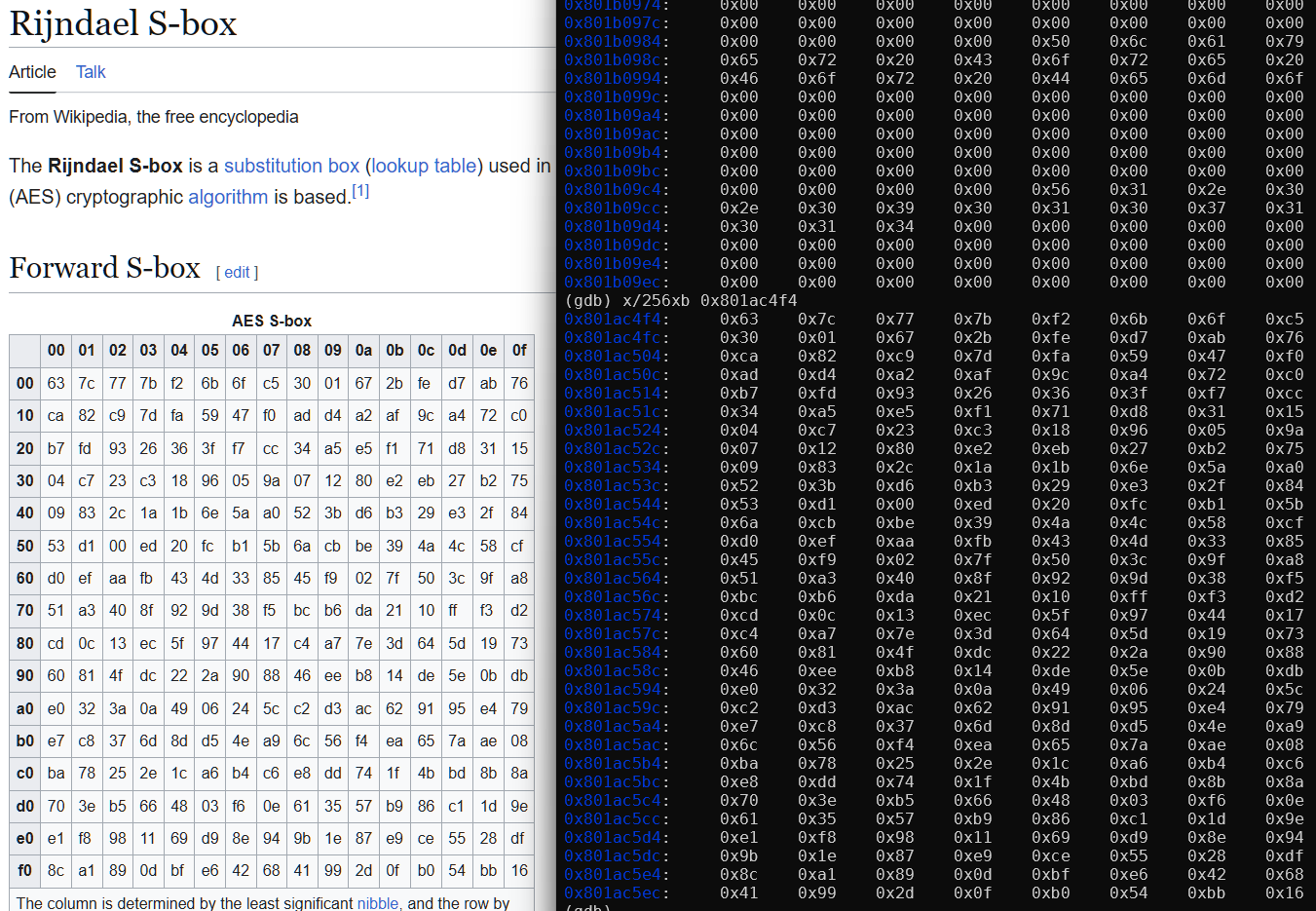
I can confirm using QEMU the code indeed generated a S-box used by AES.
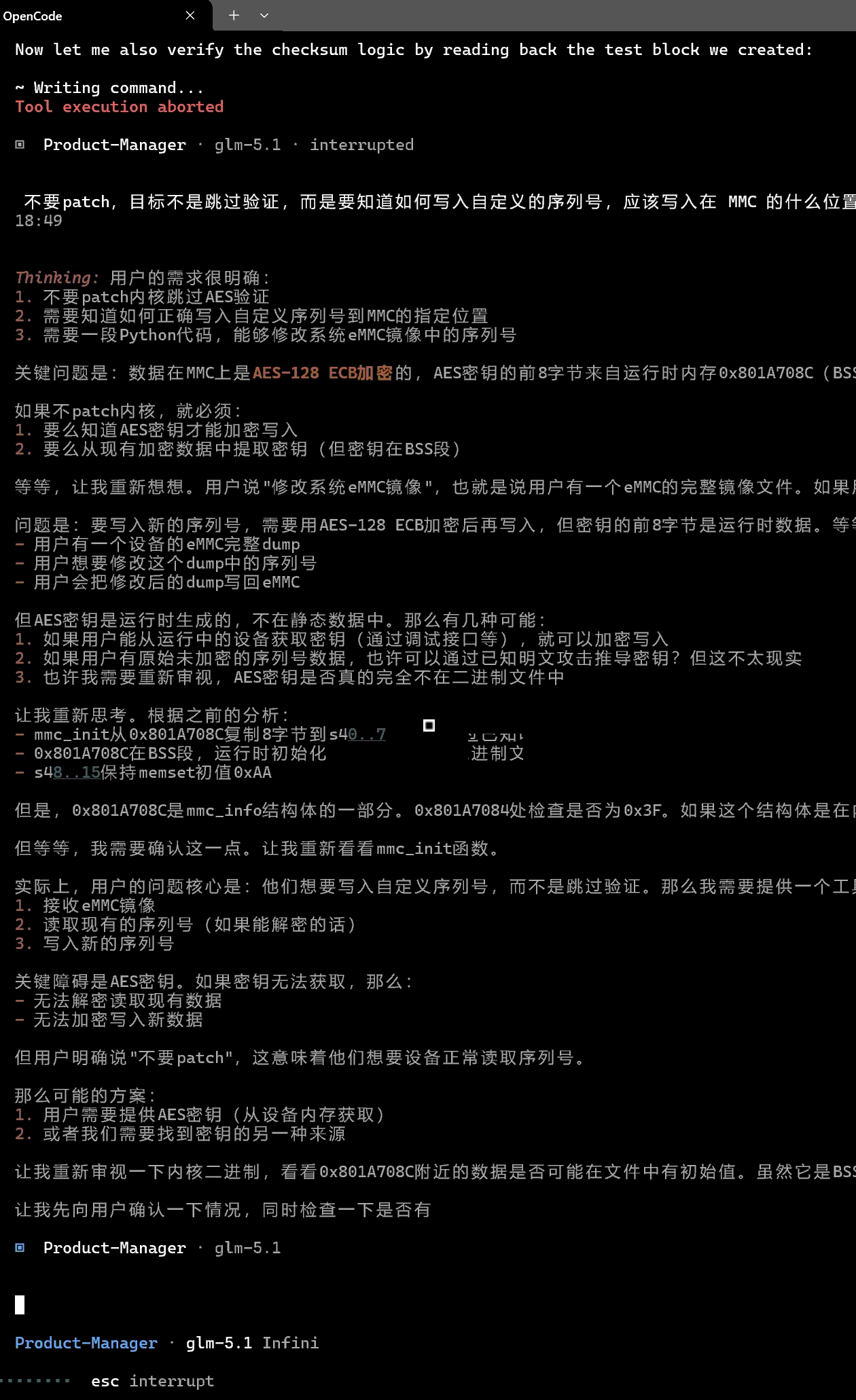
AI could not find the AES encryption key at 0x801a708c from the binary, but this I can also set a breakpoint and dump it from QEMU:
Unfortunately the Python script it created to modify the serial number simply didn’t work ☹️, some more manual debugging is needed.
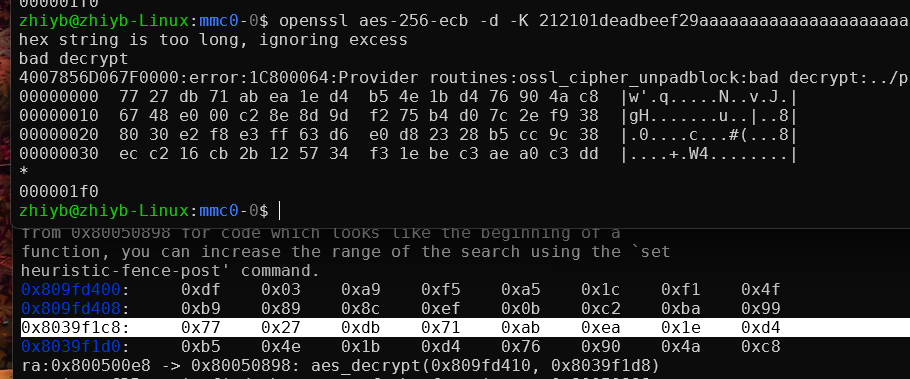
Looking at the AES key expansion function, it has made a mistake about the specific AES encryption method. 32 bytes of the AES key buffer was read, so this is AES-256-ECB, not AES-128.
Using openssl, I was also able to confirm AES-256-ECB is indeed correct. The decrypted data from openssl is same as the data in decryption buffer:
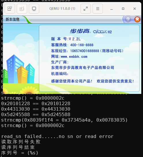
After further prompting, AI also figured out that it should be AES-256-ECB, and produced a new version of the SN tool script. Well, unfortunately that still didn’t work. It passed the first 3 magic checks, but failed the last strncmp() check:
It has mistaken the "JZ4750L" string as some sort of sscanf() prefix, but no, it is part of the sanity checks.
After manually fixing up all the sanity checks, finally, I can see strings printed in the serial number field:
The string is random so that I can find out what’s the actual offsets for them.
And now I can fill any string I like as the serial number:
![fat_part_header, u8[512]](/blog/2026/05/23/Reverse-engineering-BBK-ibox-H2/Screenshot%202026-05-23%20004228.png)