A few problems was found by further testing, a new PCB design was sent to manufacturer.
Fixed FTDI holding reset low in default UART mode, by move reset pins to pins configured as inputs in UART mode.
Varies components were moved more inside to leave more spacing for laser cut outline.
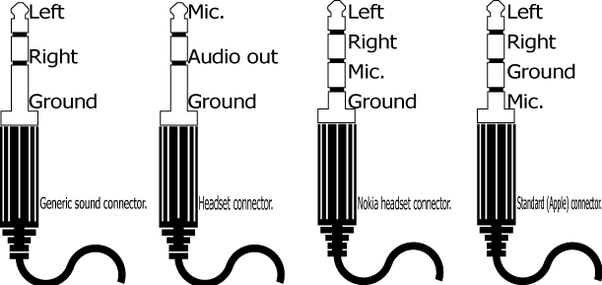
Some basic testing on the audio codec was done, includes sine wave playback and microphone loopback. It was working, but the 3.5mm jack was wired incorrectly:  Ref: How was the 3.5 mm audio jack developed and standardized?
Most (apple compatible) headsets uses type 4, but the PCB was connected assuming type 3 headsets, so that MIC would not work (reversed polarity), and audio left and right channels were mixed together (which can be fixed by pressing the answering button - that connects MIC to ground ring).
Upon reading the codec documentation, I found the codec includes a sophisticated fractional PLL, that can generate all common audio frame rates based on a 19.2MHz input frequency. Therefore, the new design uses the same 19.2MHz clock output for both USB HS PHY and audio codec.
All 4 RGB LEDs was connected in parallel with MOSFETs controlling each common anode for scanning operation. The brightness of LEDs under scanning was simulated. The brightness will degrade under scanning, but with a reduced current limiting resistor, it should still be bright enough. Corrections for LED colours and connections were also made to the schematic.
GPIO connections was changed slightly, to accommodate for new GPIO resources available. The GPIO on the audio codec is now connected for interrupts. Connections for keys and MMC card detection was also changed slightly for better routing.
Ref: c8fcb0a44512179f207b9e29207ceb355733e54a
Errata: BOOT pin jumper can be improved
Schematic: schematic.pdf
PCB design: [gallery ids=”820,823,822” type=”rectangular” link=”file”]