Got a refund on shipping fees, iteration 2 of the PCB was therefore sent for manufacturing, before the first prototype arrived.
Added pull-up resistors on audio I2C bus and MMC, changed keycap lighting to 2 RGB LEDs back mounted. However, the RGB LEDs on the bottom side of the PCB can no longer be individually controlled, and the keycap RGB LEDs can only have the same colour, due to lacking of GPIO pins and spaces.
Bottom RGB LEDs were sharing current limiting resistors. This shouldn’t be a problem if the LEDs are identical. However, the keycap RGB LEDs were also sharing another set of current limiting resistors. This can be a problem, because those 2 LEDs can be individually turned on or off. The brightness of the LEDs when both of them are on can be different to only turning on a single LED. This may be solved by scanning the LEDs interleaved instead, which will also enable individual colours for keycaps, at the cost of reduced maximum brightness.
If the brightness is not an issue, all RGB LEDs can be individually controlled while having their individual colours, by interleaved scanning. This can also save some IO pins and components. Experiments needed to check the actual brightness.
The RGB LEDs have rectangular holes on the PCB due to back mounting, however, the drill command can only drill circles. The Milling layer was used for the rectangular shape, but not sure if it works. A rectangular shape was also drawn on the Dimension layer.
No more iterations will be send to manufacturing until this PCB arrived. There may exists some other potential issues and uncertain visual effects, that can only be demonstrated by a real product. Also saves costs.
Errata: Keycap RGB LEDs sharing current limiting resistors Reset signals pulled low by FTDI during initial UART mode MIC connection is different from commonly used apple style
Schematic: schematic.pdf
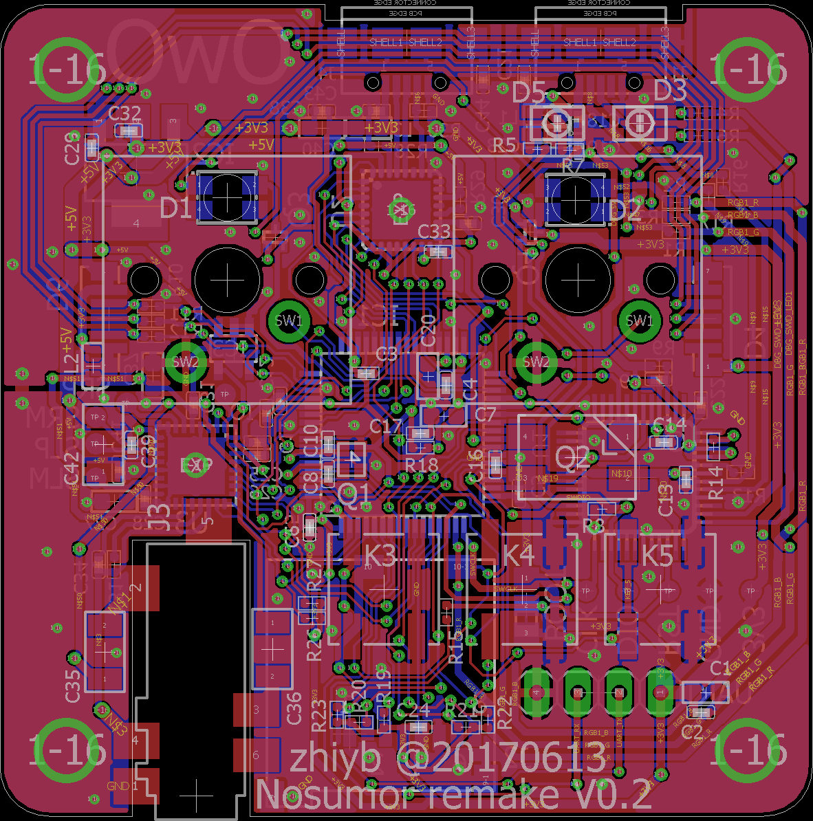
PCB layout: